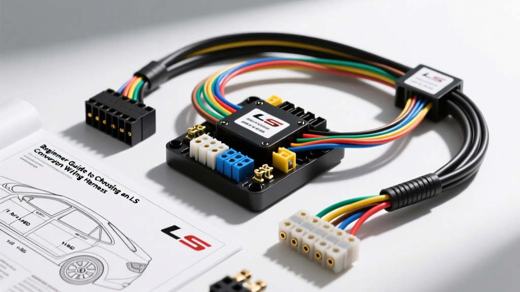
Demystifying the LS Conversion Wiring Harness
Swapping a General Motors LS engine into a classic muscle car, import, or off-road buggy is one of the most popular automotive projects in the world. However, the mechanical installation is often the easiest part. The true bottleneck for most beginners is the electrical system. An LS conversion wiring harness acts as the central nervous system of your swap, translating sensor data into fuel and spark commands while distributing power to high-draw components like fuel injectors and cooling fans.
When pulling a Gen III or Gen IV LS engine from a junkyard donor vehicle (like a 1999-2002 Camaro or a 2007+ Silverado), you are often left with a massive, tangled OEM harness designed to integrate with a factory BCM (Body Control Module), VATS (Vehicle Anti-Theft System), and complex emissions arrays. For a beginner, attempting to rework this OEM harness by cutting away dozens of unnecessary wires is a recipe for shorts, voltage drops, and endless diagnostic nightmares. This guide breaks down the fundamentals of purpose-built conversion harnesses, wire specifications, and routing best practices.
Reworked OEM vs. Standalone Conversion Harnesses
Before purchasing a harness, you must understand the two primary categories available on the aftermarket:
- Reworked OEM Harnesses: Companies take a factory GM harness, strip away the emissions and BCM wiring, and re-wrap it. These are cost-effective but require you to flash the ECU to disable VATS and rear O2 sensors. The wire lengths are also fixed to the donor vehicle's dimensions, which may not fit a classic Chevy C10 or a Nissan 240SX engine bay without stretching or looping.
- Standalone Aftermarket Harnesses: Brands like Holley, Painless Performance, and PSI build harnesses from scratch using new, high-temperature TXL wire. These are sized specifically for engine swaps, feature universal bulkhead connectors, and come with pre-terminated relays for fuel pumps and cooling fans. For beginners, a standalone harness drastically reduces troubleshooting time.
Essential Wire Gauges and Circuit Specifications
Understanding wire gauge (AWG) is critical when verifying the quality of an LS conversion wiring harness or adding your own extensions. According to the SAE J1128 standard for low-tension primary cables, automotive wire must handle specific thermal and electrical loads. Cheap import harnesses often use undersized PVC wire that melts near exhaust headers. Always look for harnesses utilizing cross-linked polyethylene (TXL or GXL) insulation.
LS1/LS2/LS3 Harness Wire Specification Chart
| Circuit Function | Typical Wire Color (GM OEM) | Required AWG Size | Connector / Terminal Type |
|---|---|---|---|
| Main ECU Battery Feed (Ignition) | Pink or Pink/Black | 10 AWG to 12 AWG | Ring Terminal / Maxi Fuse |
| Constant Battery Memory (ECU) | Orange or Orange/Black | 12 AWG | Ring Terminal / Inline Fuse |
| Main ECU Power Ground | Black | 8 AWG to 10 AWG | Heavy Duty Ring Terminal |
| Fuel Injector Control (High Side) | Pink (Shared) | 16 AWG to 18 AWG | EV1 or EV6 Metri-Pack Clip |
| Fuel Injector Control (Low Side) | Varies (e.g., Dark Blue/White) | 18 AWG to 20 AWG | EV1 or EV6 Metri-Pack Clip |
| Crankshaft Position Sensor (CKP) | Purple / White (Twisted Pair) | 22 AWG Shielded | Metri-Pack 150 Series |
| O2 Sensor Heater Ground | Black/White | 14 AWG | Spade or Ring Terminal |
ECU Pinouts and Connector Generations
A major point of confusion for beginners is matching the harness connectors to the correct ECU generation. The physical plugs on the ECU changed significantly between Gen III and Gen IV platforms.
Gen III (LS1 / LS6 / Early LM7)
Gen III ECUs (commonly referred to as the 'black box' or 'blue/green' ECU) utilize two main 40-pin connectors, totaling 80 pins.
- C1 Connector (Blue): Primarily handles injector drivers, ignition coil control, and main power grounds.
- C2 Connector (Red): Handles sensor inputs (MAF, TPS, IAT), O2 sensor signals, and serial data communication.
When buying a conversion harness for a 24x reluctor wheel Gen III engine, ensure the harness includes the correct Metri-Pack pigtails for the 24x crank sensor and the specific cam sensor located at the rear of the engine block.
Gen IV (LS2 / LS3 / L99 / 58x Reluctor)
Gen IV engines utilize a 58x reluctor wheel and require an E38, E67, or E40 ECU. These ECUs use vastly different connector layouts, often featuring a massive 94-pin connector or a combination of 38-pin and 94-pin plugs. Furthermore, Gen IV harnesses must route CAN-bus (Controller Area Network) twisted pair wires (typically 22 AWG) to the TCM (Transmission Control Module) if you are running a 4L80E or 6L80E automatic transmission. As detailed in the Holley Terminator LS Harness Manual, failing to properly terminate and shield these CAN-bus lines will result in severe transmission shifting errors and ECU communication dropouts.
Routing, Shielding, and Grounding Fundamentals
Even the most expensive standalone LS conversion wiring harness will fail if routed poorly. The engine bay is a hostile environment characterized by extreme heat, vibration, and electromagnetic interference (EMI).
Best Practices for Harness Routing
- Avoid Exhaust Proximity: Never route O2 sensor wires or main harness looms within 6 inches of exhaust headers. If crossing an exhaust pipe is unavoidable, use a heat-shielded sleeve (like DEI Titanium or Thermotec) and secure it with stainless steel zip ties.
- Use Proper Loom and Tape: Ditch the cheap plastic corrugated split-loom from the auto parts store. Wrap your harness in nylon braided sleeving or use Tesa 51036 PET cloth wiring tape. This provides a professional, OEM-style look and prevents the harness from rattling against the firewall.
- Provide a Drip Loop: When routing wires into the firewall bulkhead connector, always create a downward 'drip loop' before the wire enters the cabin. This prevents water from wicking down the wire and corroding the ECU pins inside the vehicle.
The Critical Importance of Star Grounding
Voltage drop on the ground side of the circuit is the number one cause of erratic LS idle and phantom misfire codes. Do not 'daisy chain' your grounds. The ECU power grounds, cylinder head grounds, and engine block-to-chassis grounds must all be terminated to clean, bare metal using a star-grounding method or dedicated grounding bus bar.
According to Painless Performance technical documentation, you must run a minimum 4 AWG ground strap from the passenger side cylinder head to the chassis, and another from the engine block to the starter solenoid mounting bolt. Always use a wire brush or sanding disc to remove paint, powder coat, and rust from the grounding surface before torquing the ring terminal.
Addressing VATS and Emissions for Beginners
The Vehicle Anti-Theft System (VATS) is a security feature on early LS engines that prevents the fuel injectors from firing if the correct resistor pellet is not detected in the ignition key. If you are using a junkyard harness and ECU, you have two options:
- Hardware Bypass: Solder a 2.5k ohm resistor into the VATS enable wire (usually Dark Green) at the ECU connector. This is a temporary, beginner-friendly fix to get the engine running on a test stand.
- Software Delete (Recommended): Use tuning software (like HP Tuners or EFILive) to permanently disable VATS, rear O2 sensors, EVAP, and AIR pump codes in the ECU operating system. This is the cleanest method and prevents the Check Engine Light from illuminating due to missing emissions equipment.
Summary: Investing in the Right Foundation
Skimping on your LS conversion wiring harness is the most common mistake a beginner can make. A cheap, poorly crimped harness will leave you stranded with a no-start condition or, worse, cause an electrical fire. By understanding wire gauges, respecting ECU connector generations, and adhering to strict grounding and routing protocols, you ensure your LS swap fires up on the first turn of the key and runs reliably for thousands of miles.