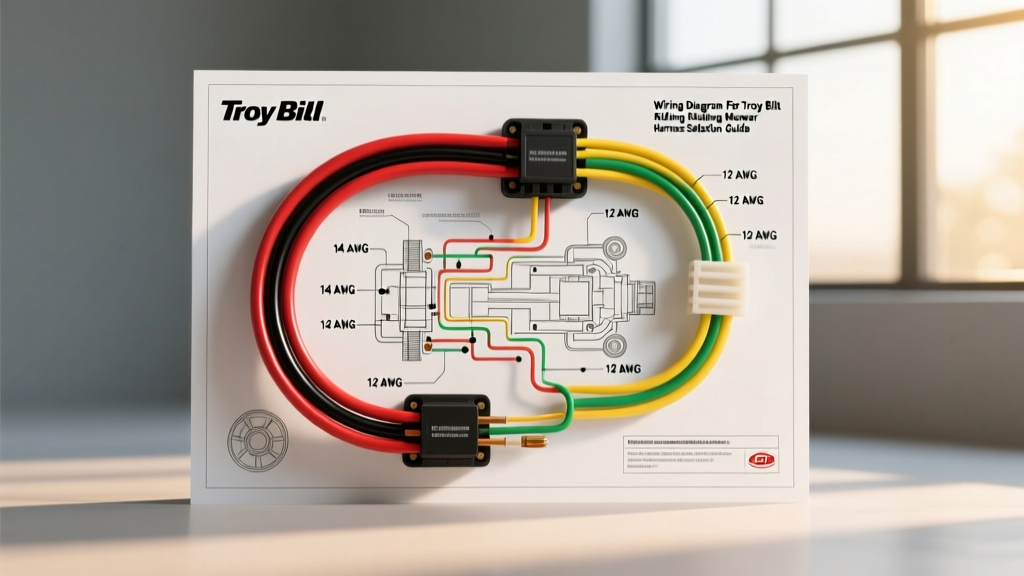
Navigating the Wiring Diagram for Troy Bilt Riding Mower Models
When diagnosing electrical faults or restoring a classic machine, securing the correct wiring diagram for Troy Bilt riding mower applications is only the first step. Because Troy-Bilt is a flagship brand of MTD Products, their electrical architectures share a common DNA across the Bronco, Mustang, and Pony series. However, selecting the right replacement wiring harness—or deciphering the schematic to build a custom loom—requires a deep understanding of MTD's low-voltage DC routing, safety interlock matrices, and PTO clutch power delivery.
In this product comparison and selection guide, we break down the electrical differences between Troy-Bilt series, compare OEM MTD harnesses against universal aftermarket alternatives, and provide the exact AWG specifications, pin configurations, and color codes you need to execute a flawless repair. Whether you are replacing a melted ignition harness or tracing a parasitic draw, this technical reference will guide your selection and installation process.
Comparing Troy-Bilt Series Electrical Architectures
Before ordering a replacement harness or printing a schematic, you must identify your mower's specific electrical platform. While the core 12V DC principles remain identical, the routing and connector types vary significantly between the primary Troy-Bilt series.
Bronco Series (Standard Lawn Tractor)
The Bronco series typically utilizes a straightforward 6-pin ignition switch matrix with a mechanical PTO engagement lever. The wiring diagram for these models features a simple safety interlock loop that grounds the ignition magneto if the operator leaves the seat while the PTO is engaged. The main harness is generally a single-piece loom running from the dash to the firewall, utilizing standard 1/4-inch insulated spade connectors.
Mustang ZTR (Zero-Turn Radius)
Mustang zero-turn mowers employ a much more complex wiring architecture. Instead of a steering column ignition, the harness routes to a dual-lap-bar safety interlock system. The wiring diagram for Troy Bilt riding mower ZTR models includes dedicated relay circuits for the electric PTO clutch, heavy-duty 10 AWG battery feeds, and dual hydrostatic release solenoids. Selecting a harness for a Mustang requires verifying the exact lap-bar switch configuration (normally open vs. normally closed), which changed midway through the 2015 production run.
Pony Series (Compact Rider)
The Pony series uses a condensed version of the Bronco harness. Due to the shorter wheelbase, the physical length of the main dash-to-engine harness is reduced by approximately 14 inches. Using a standard Bronco harness on a Pony will result in excessive slack near the steering column, which can lead to chafing against the steering shaft universal joint.
OEM MTD vs. Aftermarket Harness Selection Guide
When your wiring diagram reveals melted insulation, corroded bulkhead connectors, or brittle loom casings, you must choose between an OEM MTD replacement and a universal aftermarket kit. Below is a technical comparison to guide your purchasing decision.
| Feature | OEM MTD Harness (e.g., Part #725-1741) | Universal Aftermarket Harness |
|---|---|---|
| Connector Types | Exact-match Molex Weather-Pack and OEM spades | Generic spades; requires cutting and crimping |
| Wire Jacket | Cross-linked polyethylene (XLPE), high temp | Standard PVC, prone to melting near exhaust |
| Color Coding | Strict MTD color code adherence | Randomized; requires manual tracing and labeling |
| Interlock Diodes | Pre-installed blocking diodes in seat circuit | Missing; must be soldered in manually |
| Best Application | Direct plug-and-play restoration | Custom builds or heavily modified tractors |
For 90% of repairs, sourcing an OEM harness via Jacks Small Engines or directly through MTD Parts is the superior choice. The inclusion of pre-installed blocking diodes in the seat safety circuit is a critical factor that most universal kits omit, leading to immediate backfires or starter engagement upon sitting down.
Core Wiring Diagram Tracing: Component Pinouts
To effectively use your wiring diagram for Troy Bilt riding mower troubleshooting, you must understand the pinout logic of the central components. The most common failure point is the 6-pin ignition switch.
6-Pin Ignition Switch Terminal Matrix
Troy-Bilt uses a standard 6-prong ignition switch (often MTD part #925-1741A). When reading the schematic, locate these terminal designations:
- B (Battery): Receives constant 12V+ from the starter solenoid battery post. Typically 12 AWG Red wire.
- S (Solenoid): Sends 12V+ to the starter solenoid trigger tab only when turned to 'START'. Typically 14 AWG Red/White tracer.
- M (Magneto): Grounds the ignition coil to kill the engine when turned to 'OFF'. Typically 14 AWG Orange wire.
- L (Lights): Provides 12V+ to the headlight circuit in 'RUN' and 'START'. Typically 16 AWG White wire.
- G (Ground): Chassis ground reference for the switch illumination and internal resistor. 16 AWG Black.
- A (Accessory): Provides 12V+ to the PTO clutch relay coil when the PTO switch is pulled. 14 AWG Green.
Electric PTO Clutch & Relay Circuit
Modern Troy-Bilt mowers utilize an electromagnetic PTO clutch (Ogura or Warner) that draws between 2.5 and 3.5 Amps at 12V DC. The wiring diagram will show this component wired through a 30-amp automotive-style relay. Never wire the PTO clutch directly through the dashboard toggle switch. The high amperage will melt the dashboard switch contacts within minutes. The relay coil is triggered by the dashboard switch (drawing less than 0.2 Amps), while the heavy clutch load is pulled directly from the battery via a fused 10 AWG red feed wire.
Wire Gauge (AWG) & Color Code Specifications
Adhering to the correct American Wire Gauge (AWG) is critical to prevent voltage drop and harness fires. According to SAE J1128 standards for low-tension primary cables, the following gauges must be used when repairing or fabricating a Troy-Bilt harness:
| Circuit Application | MTD Standard Color | Required AWG Size | Fuse Rating |
|---|---|---|---|
| Battery to Solenoid / Starter | Red | 8 AWG or 10 AWG | Inline 30A Maxi-Fuse |
| Solenoid to Ignition Switch (B) | Red | 12 AWG | 20A Blade Fuse |
| PTO Clutch Power Feed | Red (Relay to Clutch) | 12 AWG | 10A Blade Fuse |
| Safety Interlocks / Signal | Orange / Purple | 16 AWG or 18 AWG | Unfused (Ground side) |
| Stator AC Output | Yellow (x2) | 14 AWG | N/A (AC Voltage) |
| Voltage Regulator DC Out | White | 12 AWG | 20A Inline Fuse |
Stator and Voltage Regulator Routing
The charging system on a Troy-Bilt riding mower relies on an under-flywheel stator producing 28V to 35V AC. The wiring diagram will show two Yellow wires routing from the stator to the voltage regulator/rectifier. The regulator converts this to 13.8V - 14.4V DC, which exits on a single White wire to recharge the 12V battery. If your White wire shows signs of melting, it is almost always caused by a failing battery that is forcing the regulator to operate at maximum continuous amperage, overheating the 12 AWG circuit.
Troubleshooting Common Harness Failures
When your wiring diagram indicates a closed circuit but the component fails to operate, use this symptom-cause-fix decision tree:
- Symptom: Starter clicks once, but engine does not crank.
- Cause: Voltage drop across the 4-post starter solenoid or corroded ring terminals.
- Fix: Use a multimeter to measure voltage drop across the large solenoid posts while cranking. A drop greater than 0.5V indicates internal solenoid pitting. Replace with MTD part #925-06119A and apply dielectric grease to the 8 AWG ring terminals.
- Symptom: PTO clutch engages, but blows the dash fuse immediately.
- Cause: Short to ground in the Green PTO trigger wire, or a failed clutch coil (internal short).
- Fix: Disconnect the clutch connector. Measure resistance across the clutch terminals. A healthy Ogura clutch should read between 2.5 and 4.5 Ohms. If it reads 0 Ohms, the clutch coil is internally shorted and must be replaced. If the clutch tests fine, trace the Green wire back to the relay for chafing against the mower deck.
- Symptom: Engine dies instantly when the brake pedal is released.
- Cause: Faulty brake pedal safety switch or misadjusted switch plunger.
- Fix: Locate the brake switch under the chassis. Bypass the switch temporarily with a jumper wire to confirm it is the source of the open circuit. Adjust the physical mounting bracket so the switch plunger is fully depressed when the brake is engaged.
Final Selection and Installation Advice
Securing the correct wiring diagram for Troy Bilt riding mower applications is essential, but pairing it with the right physical components ensures long-term reliability. Always opt for OEM MTD harnesses to guarantee proper Weather-Pack seals and correct blocking diode integration. When making field repairs, abandon electrical tape in favor of adhesive-lined heat shrink tubing and nylon braided loom to protect against the extreme vibration and heat generated by the small engine block. By respecting the AWG requirements and safety interlock logic detailed above, your Troy-Bilt electrical system will deliver reliable starts and seamless PTO engagement for years to come.